Connection to PC is usually done through RS232 9 pin serial connector with the connector as shown in the somewhat lower. Note that the pin is important to be used in the circuit that we make is pin Request To Send (RTS), Data Terminal Ready (DTR) and Ground (GND). With the pin number 7 (RTS), 4 (DTR) and 5 (GND).
Component
Resistor 1K2 ohm
Diode 1N4148
4N33 optocoupler or Toshiba TLP521-1, TLP-521-2
PCB hole - for prototyping
Mic Connectors
Small stereo connector (make)
Mono connectors - for CW Rig (optional)
9pin RS232 connector (female)
Stereo cable a few meters

Interface circuit using the 4N33 for PSK31, RTTY, CW

Interface circuit using the TLP521

Interface circuit using PC817
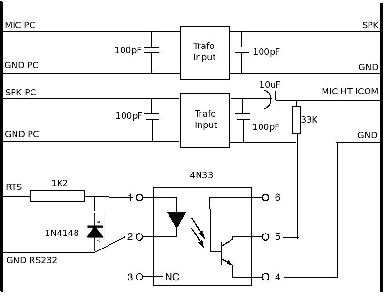
RF protection circuit with feedback
Component
Resistor 1K2 ohm
Diode 1N4148
4N33 optocoupler or Toshiba TLP521-1, TLP-521-2
1:1 600 ohm transformer (rather difficult to find it)
100pF Capacitor
PCB hole - for prototyping
Mic Connectors
Small stereo connector (male)
Mono connectors - for CW Rig (optional)
9pin RS232 connector (female)
Stereo cable a few meters

Interface circuit for PSK31, RTTY, CW with RF protection Feedback

Interface circuit using the TLP521

Interface circuit using PC817
Circuit for Handy Transceiver
This circuit is OK for HT Alinco

Interface with TLP521 series for Handy Transceiver

Interface circuit with PC817 for Handy Transceiver
Circuit for Handy Transceiver ICOM
This series is better for HT ICOM
Interface with the 4N33 series for HT ICOM
Audio conversion circuit for CW to CW Key to Fldigi

RS232 9pin

RS232 9pin
The pins used are pin 7 (RTS), pin 4 (DTR) and pin 5 (GND).
ICOM MIC Connector
To facilitate colleagues not to search again attached the pins of the connector Mic ICOM.

ICOM Mic connector
Pin that is used is
pin 1 (MIC input)
pin 7 (Ground MIC)
pin 6 (PTT Ground)
pin 5 (PTT)
ICOM BACK PIN NO.: FUNCTION
4 8 12 16 20 24
3 7 11 15 19 23
2 6 10 14 18 22
1 5 9 13 17 21
1:Output from the squelch control stage. (+8V when the squelch is ON.)
2:13.8 volts DC interlocked with the power switch
3:Connected to the push-to-talk, T/R switch. When grounded, the transceiver changes to the transmit mode.
4:Output from the receive detector stage. Fixed output regardless of AF output or AF gain.
5:Output from the transmit MIC amplifier stage.(Input for the MIC gain control stage.)
6: 8 volts DC output while transmitting. (Maximum output current is 5mA.)
7:Input for external ALC voltage.
8:Ground.
9:Input for RTTY keying (MARK: HIGH level, SPACE: LOW level). The levels for MARK and SPACE may be reversed with an internal switch.
10:NC (no connection).
11:Input for TRANSVERTER control. Apply 8 volts DC to use a transverter with the IC-751 A.
12:Reference voltage output for band switching.
13:Band Control Voltage output.
14-24: NC (no connection).
How it Works The circuit
Work interface circuit for digital communications is actually relatively simple.
Software HAMSCOPE or FLDIGI or digital communications software running on a PC.
HAMSCOPE software can be set to control Pin RS232 RTS to be HIGH if it transmits.
HIGH signal on the RTS will enable Opto Coupler to be short on its output. If Opto Coupler connector Mic at the rig will transmit.
For CW operation, we can use the RS232 DTR pin of the plug into the Jack in the Rig through a series of CW Opto Coupler. So that we can type the keyboard only to send the CW.
To ensure there is no RF feedback from the radio equipment, we typically will use the Input Transformer with 100pF capacitors on the two sides of its equipment to isolate the PC from the Rig.
The problem is somewhat dangerous to the continuation PC to Rig ever experienced by the writer only to the volume of the rig. Make sure the volume is not too large, because if too much is likely to make the sound card in the PC becomes damaged.

73, Tnx FB OM; excelent information home page.
ReplyDeleteDaniel - PU4YJS
thanks for visited Daniel...hpe see u on the band '73 de YC1CWK
Deletehai bro i need your ..plz reply my email..kishenraj93@gmail.com
DeleteHello mister, needed connect Yaesu Ft 1000 Mark V to Pc for full mode, PSK31,JT65,CW and more, watch circuit recommendations ?, thanks for reading ! - LU5FCI Horace - Argentine
ReplyDeletehai bro... please reply my email.. kishenraj93@gmail.com
ReplyDeleteNice page to refer to, thanks :))
ReplyDelete73 yt1zvm
ReplyDeleteThank You and that i have a dandy provide: How To Become A House Renovation house renovation experts
ReplyDelete